Page 2 of 2
Re: Dynamos and powering stuff
Posted: Thu Sep 12, 2013 9:54 am
by composite
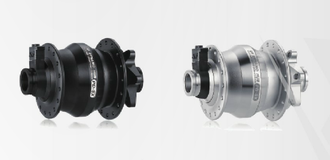
So I lost track of this thread and it went on some. Thanks for the extra info. I decided to go with the SP hub and have pre-ordered the PD-8X which is the new 15mm axle version. It should be out in October. It also has some efficiency improvements and less drag than the QR only version.
The lack of being able to service the bearings myself was a concern but as I'm building 2 front wheels for the bike it will go on (one dynamo, one normal) it will "increase" the life. I think they said some where that it had been tested to 10 000miles (I hope I'm remembering that right) which will take me a while to do on one wheel let alone 2. Of course it will be a bit of a pain to strip the wheel and send it back to them but as I'm building the wheels myself it's my hassle not something I will have to pay someone else for.
So need to order the Revo light next and keep researching the USB interface bit. :)
@slowupslowdown Is the Gamin powering OK via the Kemo box? Also what are your thoughts about how waterproof it looks?
Re: Dynamos and powering stuff
Posted: Thu Sep 12, 2013 10:08 am
by paul78
If you haven't already ordered the Revo light then speak to K-Lite in Australia ( you can contact Kerry easily via facebook)
The K-Lite is a lot better suited when looking at charging via usb etc.
I have just has K-lite make me a USB switching box for my SP/Revo combo but wished I had gone with the K-lite option originally
Re: Dynamos and powering stuff
Posted: Thu Sep 12, 2013 1:19 pm
by composite
Thanks for that, the k-lite lights look pretty good.
Links for others interested.
http://www.klite.com.au/ (half finished site)
https://www.facebook.com/kLite.com.au
Re: Dynamos and powering stuff
Posted: Thu Nov 07, 2013 11:32 am
by Mart
There also is a DIY option (if your handy with a soldering iron)
http://www.pilom.com/BicycleElectronics ... rcuits.htm
Its a little above my skill level tho

Re: Dynamos and powering stuff
Posted: Thu Nov 07, 2013 12:16 pm
by BenS
If you're handy with a soldering iron (and the German language) there are some resources here:
http://www.forumslader.de/12V-Version-m ... 209.0.html
They have done quite a bit of work using diferent rectifier configurations (i.e. ac out of the dynamo to dc to charge batteries). From some of the pictures you can see how you can get a fair bit more than 3W out of a dynamo hub at modest speeds by choosing the correct rectifier.
I have built a widget that plugs between my dynamo hub (SP something) and the light (homebuilt) which rectifies the current and charges a bank of capacitors for some standlight capability. It seems to work well, it's just waiting for some proper weatherproofing.
Re: Dynamos and powering stuff
Posted: Thu Nov 07, 2013 2:06 pm
by evilgoat
I have an SP dynohub on my commute bike.
I built a light unit with twin XP-g leds and a supercap circuit which gives about 2-3 minutes high intensity standlight on one of the leds. which then drops off but is normally still lit about 20 minutes later. plenty to be seen at junctions. Calculated output is around 400lumens.
I made the light with a clear housing so there was plenty of light spill around the front wheel and sideways for max visibility.
It's pretty simple and if anyone's interested I can upload pics and circuit diagram.
Next plan is to add another led (600 lumens) and output for the USB charger I made.
Re: Dynamos and powering stuff
Posted: Thu Nov 07, 2013 9:09 pm
by composite
Pics or it didn't happen.

Please. :D
Re: Dynamos and powering stuff
Posted: Fri Nov 08, 2013 2:32 pm
by evilgoat
Duh, i didn't take any pics of the actual circuit board, but here is the housing:
https://plus.google.com/103846366653187 ... b5ZCYVLPjm
and this is the circuit:
https://plus.google.com/103846366653187 ... UjTxb9yoHB
it's pretty simple really.
Re: Dynamos and powering stuff
Posted: Tue Nov 12, 2013 5:27 pm
by BenS
Some pictures of my setup. Dynamo plugs into the circuit below, there is a TVS diode (can't remember circuit symbol) to limit any high voltage spikes or capacitor overvoltage. The TVS diode is linked to a thermal switch so if it gets too hot it disconnects the circuit from the dynamo. The two capacitors within the bridge circuit are to increase the voltage and hence output power at lower speeds. The capacitors are 3 5.4v 2.5F supercaps 3 series connected, 2 in parallel, 6 in all giving a capacitance of ~1.6F capable of having 16v applied.

The circuit was built up on some veroboard and is shown prior to a bit of heat shrink and plastidip

and on the bike once dipped in plastidip

The light itself is a taskled Maxflex board driving 3 Cree XMLs connected in series. The maxflex board will step up the voltage to drive the LEDs when the voltage on the capacitors is less than the forward voltage of the LEDs (~8.8v). Once fully charged it gives a reasonable standlight that you can see by for about 60+ secs. Going faster charges the capacitors and the board then stops current regulating and the current overflows through the maxflex's diode/inductor enabling the LED to be brighter and limiting the voltage on the capacitors. This does require the light to be constantly connected and switched on otherwise it is possible to get a high voltage on the capacitors that could damage the drive circuit or LED.
Not sure how well I've explained that?


